ASTM G225-26
 Preview
Summary
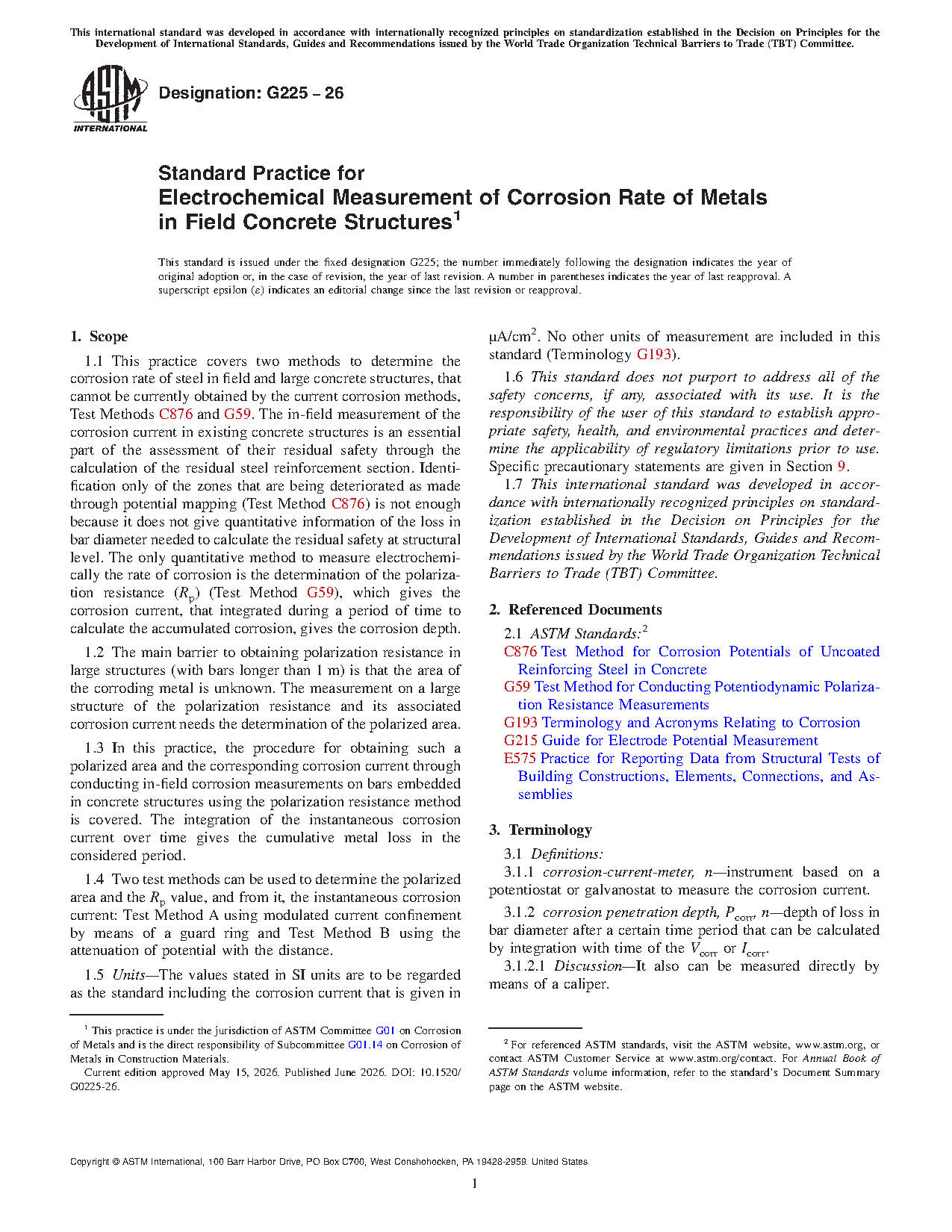
1.1 This practice covers two methods to determine the corrosion rate of steel in field and large concrete structures, that cannot be currently obtained by the current corrosion methods, Test Methods C876 and G59. The in-field measurement of the corrosion current in existing concrete structures is an essential part of the assessment of their residual safety through the calculation of the residual steel reinforcement section. Identification only of the zones that are being deteriorated as made through potential mapping (Test Method C876) is not enough because it does not give quantitative information of the loss in bar diameter needed to calculate the residual safety at structural level. The only quantitative method to measure electrochemically the rate of corrosion is the determination of the polarization resistance (Rp) (Test Method G59), which gives the corrosion current, that integrated during a period of time to calculate the accumulated corrosion, gives the corrosion depth.
1.2 The main barrier to obtaining polarization resistance in large structures (with bars longer than 1 m) is that the area of the corroding metal is unknown. The measurement on a large structure of the polarization resistance and its associated corrosion current needs the determination of the polarized area.
1.3 In this practice, the procedure for obtaining such a polarized area and the corresponding corrosion current through conducting in-field corrosion measurements on bars embedded in concrete structures using the polarization resistance method is covered. The integration of the instantaneous corrosion current over time gives the cumulative metal loss in the considered period.
1.4 Two test methods can be used to determine the polarized area and the Rp value, and from it, the instantaneous corrosion current: Test Method A using modulated current confinement by means of a guard ring and Test Method B using the attenuation of potential with the distance.
1.5 Units—The values stated in SI units are to be regarded as the standard including the corrosion current that is given in µA/cm2. No other units of measurement are included in this standard (Terminology G193).
1.6 This standard does not purport to address all of the safety concerns, if any, associated with its use. It is the responsibility of the user of this standard to establish appropriate safety, health, and environmental practices and determine the applicability of regulatory limitations prior to use. Specific precautionary statements are given in Section 9.
1.7 This international standard was developed in accordance with internationally recognized principles on standardization established in the Decision on Principles for the Development of International Standards, Guides and Recommendations issued by the World Trade Organization Technical Barriers to Trade (TBT) Committee.
Significance and Use:
5.1 Because of its simplicity and accuracy, the polarization resistance technique has been widely used in the laboratory in numerous metal/electrolyte systems (2, 7-10). However, its application in real-size elements is not straightforward because of the need for referral to the actual polarized area (3). A quasi-infinite area cannot be wholly polarized because it is not feasible to use a counter electrode of the same size as the reinforcement. Therefore, small CEs have to be used that polarize only a small portion of the bars around where they are placed. The distance reached from the border of the CE until a distance (named the critical length, Lcrit), (Fig. 1) (3) which depends on the square root of the ratio between the actual concrete ohmic resistance (moisture level) and the polarization resistance (1, 4).
5.2 To overcome the problem of identifying the polarized area, two main test methods can be used (1, 4):
5.2.1 Test Method A—Confining the current by means of a so named “guard ring” (1).
5.2.2 Test Method B—Measuring and determining the potential attenuation with the distance along the bar from the point where the counter electrode is placed (4).
5.3 These test methods can be applied to any element geometry or concrete type. The concrete cover thickness does not influence the results (depths higher than 1 m have been tested) and neither does the number of bars. The corrosion is only measured, however, in the bar layer closer to the surface as this bar layer shields the deeper penetration of the electrical current.
5.4 Measurements can be performed in cracked concrete. However, locations with major voids, delaminations, or large cracks (>1 mm) within the concrete may give wrong values particularly in wet concrete, because these defects may cause the signal to deviate from the required electrolytic path resulting in erroneous readings.
5.5 There are several uses of the Rp measurements:
5.5.1 Characterizing the corrosion condition and discriminating between corroding and non-corroding (passivated) zones;
5.5.2 To quantify the degree of corrosion as the loss in rebar cross section from the values of Icorr values. This calculation enables the introduction of the metal losses into structural models to assess the structural limit states with respect to cover cracking, loss of bond, and loss of load-bearing capacity; and
5.5.3 To evaluate the effectiveness of repair work.
5.6 The corrosion current values shall be interpreted by specialists or skilled engineers experienced in the field of corrosion testing and structural evaluation.
Technical characteristics
| Publisher | American Society for Testing and Materials (ASTM International) |
| Publication Date | 05/15/2026 |
| Collection | |
| Page Count | 17 |
| EAN | --- |
| ISBN | --- |
| Weight (in grams) | --- |
Previous versions
Collections list